

 1:1 Satellite L-Band Redundancy Switch
 1:1 Satellite L-Band Redundancy Switch
BLR-4X
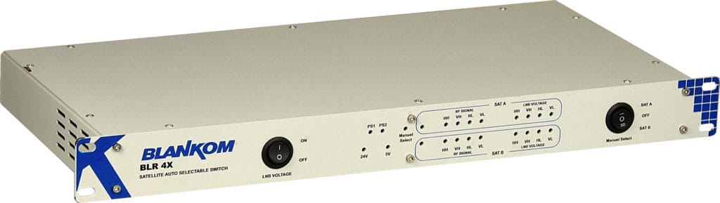
BLANKOM BLR-4X switches four satellite IF paths between a primary and a backup Quattro LNB source. Automatic level monitoring, manual selection and dual internal redundant power supplies support reception continuity in DVB/IPTV headends.

Ordering Guide
- Specify two compatible four-path sources, downstream IF mapping, source levels and LNB powering plan
Technical Overview
Two sets of four IF inputs connect SAT A and SAT B. SAT A is the preferred source. When a monitored SAT A path loses sufficient level, the unit switches to SAT B, continues monitoring SAT A and returns when the primary signal recovers.
The four outputs carry VL, HL, VH and HH satellite IF paths in the 950–2150 MHz band. This is RF source selection before the headend receivers, not IP switching, transport-stream decoding or a high-power amplifier output switch. The backup paths must deliver the services and IF mapping required by downstream receivers.
The front panel offers SAT A, automatic and SAT B modes, plus input/output and power status indications. Dual internal power supplies reduce dependence on a single supply. RF switching alone does not guarantee glitch-free decoded video during an input failure; the receiver must reacquire a valid signal.
At a Glance
INPUT
- Inputs: 2 × 4 SAT-IF paths; primary A and backup B
- LNB support: Quattro LNB or optical O/E receiver; LNB supply 13/18 V, maximum 600 mA
OUTPUT
- Outputs: 4: VL, HL, VH, HH
FEATURES
- Automatic switching: Monitors primary path level; automatic backup selection and return to primary; published trigger below 65 dBµV
- Operating modes: SAT A / Automatic / SAT B
- Status indication: Input, output and PSU LEDs
- Power: Dual internal redundant PSUs; published supply 220 V AC, 50 Hz
Ordering Guide
- Ordering: Specify two compatible four-path sources, downstream IF mapping, source levels and LNB powering plan
Key Features
- Automatic switching: Monitors primary path level; automatic backup selection and return to primary; published trigger below 65 dBµV
- Operating modes: SAT A / Automatic / SAT B
- Status indication: Input, output and PSU LEDs
- Power: Dual internal redundant PSUs; published supply 220 V AC, 50 Hz
System Diagram
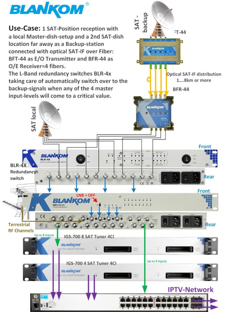
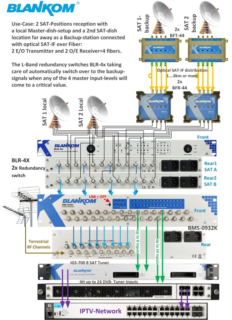
Manufacturer reference diagram. The complete topology and required accessories depend on the project.
Typical Applications
Dual-dish headend reception
Connect matching four-path primary and backup LNB feeds ahead of the receiving equipment. Ensure the backup source provides the required programme services and frequency/polarity mapping.
LNB maintenance and replacement
Use manual A/B selection to work on one source while the other feeds the headend. Assess receiver reacquisition behaviour during the planned switchover.
Optical satellite distribution backup
Use compatible O/E receiver IF outputs as the alternate source set. Calculate signal levels and LNB/DC arrangements for the complete reception chain.
Product Images
Family reference illustration; the depicted housing or model may differ from the selected variant.

Technical Specifications
| Parameter | Specification |
|---|---|
| Inputs | 2 × 4 SAT-IF paths; primary A and backup B |
| Outputs | 4: VL, HL, VH, HH |
| Frequency range | 950–2150 MHz |
| Automatic switching | Monitors primary path level; automatic backup selection and return to primary; published trigger below 65 dBµV |
| Operating modes | SAT A / Automatic / SAT B |
| LNB support | Quattro LNB or optical O/E receiver; LNB supply 13/18 V, maximum 600 mA |
| Maximum levels | Input 98 dBµV; output 102 dBµV (IMA3 reference) |
| Return loss and isolation | Input/output 10/14 dB; SAT-SAT isolation >33 dB |
| Status indication | Input, output and PSU LEDs |
| Power | Dual internal redundant PSUs; published supply 220 V AC, 50 Hz |
| Dimensions | 19-inch, 1U; published enclosure 440 × 240 × 45 mm |
| Ordering | Specify two compatible four-path sources, downstream IF mapping, source levels and LNB powering plan |
The listed values follow the official technical reference. Select the required model and configuration before ordering.
Technical FAQ
1. What does 1:1 redundancy mean here?
Inputs: 2 × 4 SAT-IF paths; primary A and backup B. Outputs: 4: VL, HL, VH, HH.
2. Which frequency band is switched?
Frequency range: 950–2150 MHz.
3. What triggers automatic changeover?
Automatic switching: Monitors primary path level; automatic backup selection and return to primary; published trigger below 65 dBµV.
4. Can a source be selected manually?
Operating modes: SAT A / Automatic / SAT B.
5. Which LNB and optical sources are listed?
LNB support: Quattro LNB or optical O/E receiver; LNB supply 13/18 V, maximum 600 mA.
6. What are the maximum RF levels?
Maximum levels: Input 98 dBµV; output 102 dBµV (IMA3 reference).
7. What return loss and isolation are specified?
Return loss and isolation: Input/output 10/14 dB; SAT-SAT isolation >33 dB.
8. How are faults and active paths indicated?
Status indication: Input, output and PSU LEDs.
9. Are redundant power supplies included?
Power: Dual internal redundant PSUs; published supply 220 V AC, 50 Hz.
10. What must be planned before installation?
Dimensions: 19-inch, 1U; published enclosure 440 × 240 × 45 mm. Ordering: Specify two compatible four-path sources, downstream IF mapping, source levels and LNB powering plan.