RF over Fiber
BPF-11-4/BFR-11


Ordering Guide
BLANKOM BPF-11-4/BFR-11
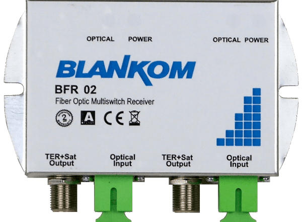
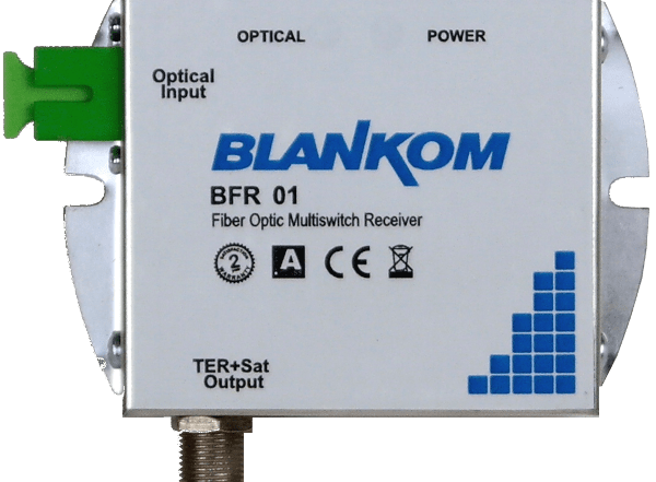
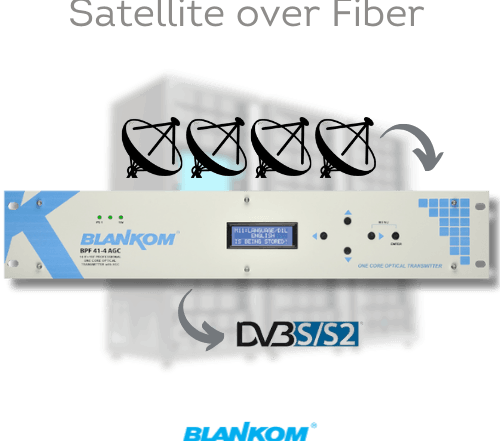
BPF-11-4 optical transmitter, 4 mW; matching BFR-11 optical receiver.
At a Glance
- Inputs — 4 × SAT-IF + 1 × terrestrial RF; 5 F-female, 75 Ω
- Outputs — 1 × SC/APC at the transmitter. The BFR-11 recovers 4 SAT-IF feeds and one terrestrial feed.
- Features — One satellite position and terrestrial RF on one fiber · 4 mW
- Ordering guide — BPF-11-4 optical transmitter, 4 mW; matching BFR-11 optical receiver.
Transmitter and Receiver


System Diagram

Technical Overview
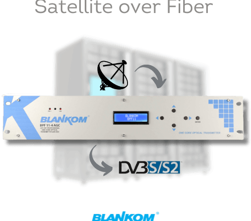
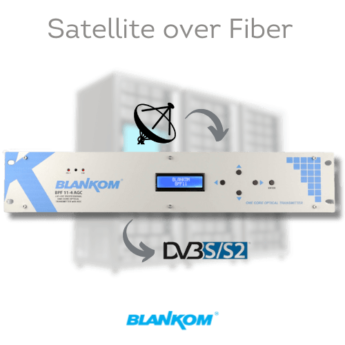
The transmitter combines 4 satellite IF paths and a terrestrial path by coarse wavelength division multiplexing (CWDM). At the far end, the BFR-11 presents each band and polarization on its own RF output, ready for a multiswitch or headend tuner.
Model comparison
| Catalog system | Satellite positions | Fibers | Transmitter optical output |
|---|---|---|---|
| BPF-11-4/BFR-11 | 1 | 1 | 4 mW |
| BPF-11-8/BFR-11 | 1 | 1 | 8 mW |
| BPF-41-4/BFR-41 | 4 | 1 | 4 mW |
| BPF-41-8/BFR-41 | 4 | 1 | 8 mW |
| BPF-44/BFR-44 | 1 | 4 | 2–5 mW |
Typical Applications
Headend installation
Connect a roof-mounted dish to a remote headend. Feed the four recovered SAT-IF paths and terrestrial RF to a local multiswitch.
Optical link planning
Use the 4 mW rating as the launch power when calculating the level at each receiver. Include splitter, connector and fiber losses in the path budget.

BLANKOM BPF-11-4/BFR-11 Application Diagram
Technical Specifications
| Transmitter RF inputs | 4 SAT-IF + 1 terrestrial; 5 × F-female, 75 Ω |
|---|---|
| Satellite IF band | 950–2150 MHz |
| Terrestrial RF band | 47–870 MHz |
| Optical port | 1 × SC/APC, single-mode CWDM |
| Transmitter optical output | 4 mW |
| Receiver RF outputs | 4 SAT-IF + 1 terrestrial |
| Transmitter form factor | 19-inch rack, 2U |
Specifications may change. Check the optical input range and the loss budget for the selected configuration.
Engineering FAQ
What does “-4” mean?
The suffix identifies the transmitter optical output power, 4 mW. The receiver model is BFR-11.
Can the optical line feed more than one headend?
An optical splitter can feed additional receivers. Check transmitter output, splitter and connector loss, fiber attenuation and the receiver input range for every branch.