

 Optical SAT outlet for one receiver
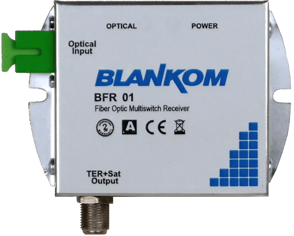
BFR-01

Ordering guide
BLANKOM BFR-01
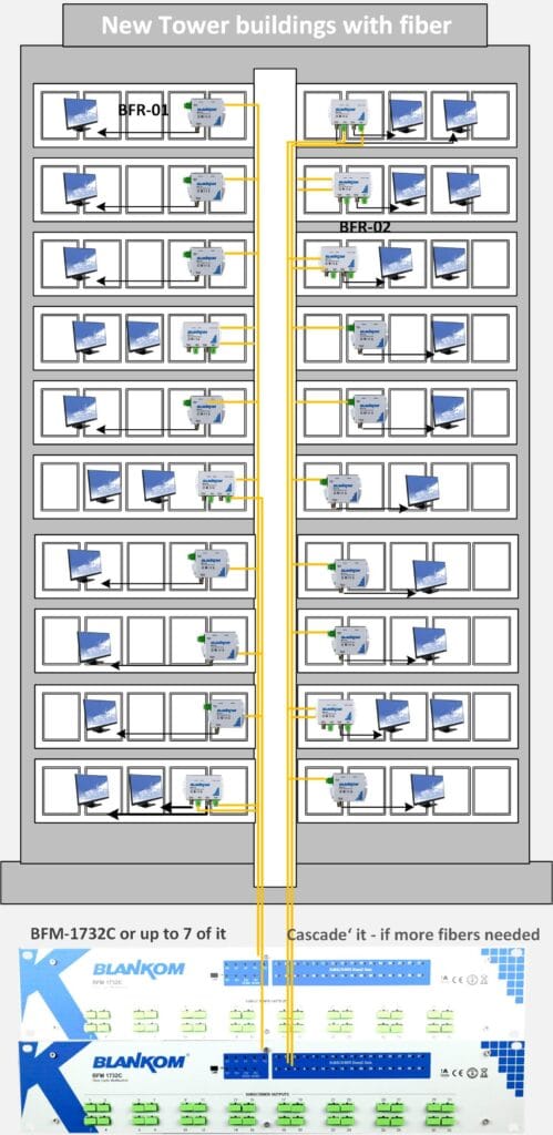
Select BFR-01 for one tuner and one fibre. Use BFR-02 for two tuner paths where two fibres are available.
At a glance
Connections and equipment
Signal path · One fibre · One receiver · Receiver-powered

System diagram
Technical overview
The connected tuner sends 13/18 V for polarisation, 0/22 kHz for the low/high band and DiSEqC for the satellite position into the outlet’s coaxial F output. The outlet relays the commands upstream at 1310 nm. The BFM-1732C receives them at its optical subscriber port, selects the requested SAT-IF path and sends it downstream at 1550 nm.
Typical applications
Use one outlet at a single TV position in an apartment or hotel room. The fibre run ends beside the receiver so the final connection remains a short coaxial lead.
System selection
Select BFR-01 for one tuner and one fibre. Use BFR-02 for two tuner paths where two fibres are available.

BLANKOM BFR-01 Application Diagram
Technical specifications
| Inputs | 1 × SC/APC |
|---|---|
| Outputs | 1 × F, 75 Ω |
| Satellite IF range | 950–2150 MHz |
| Terrestrial RF range | 47–870 MHz |
| Optical directions | 1550 nm downstream / 1310 nm upstream |
| Maximum optical input | 2 mW |
| Power supply | From the connected satellite receiver |
| Dimensions | 73 × 46 × 33 mm |
| Operating temperature | −15 … +40 °C |
Technical data applies to the stated model.
Engineering FAQ
Where does the LNB selection command originate?
The tuner applies 13/18 V, 0/22 kHz and DiSEqC to the F output. BFR-01 transports those commands to the headend through the optical return channel.
What should be specified for a quotation?
Select BFR-01 for one tuner and one fibre. Use BFR-02 for two tuner paths where two fibres are available.